 Back in late 1979, Milton
Bradley created a programmable 6 wheeled vehicle called
the Big Trak. It was capable of performing 8 different
functions and was considered programmable because it
could store and play back a sequence of up to 16 of those
functions. After reading the article in Ciarcia's Circuit
Cellar Volume III, which was about creating a remote
control for the Big Trak, my friend Louie ask for, and
received one of these for Christmas of '82. We quickly
exhausted all the creativeness we could muster out
of Forward, Reverse, Left, Right, Fire, Repeat,
Delay, & Dump trailer and decided that it was time
that we take it apart and do something else with
it.
Back in late 1979, Milton
Bradley created a programmable 6 wheeled vehicle called
the Big Trak. It was capable of performing 8 different
functions and was considered programmable because it
could store and play back a sequence of up to 16 of those
functions. After reading the article in Ciarcia's Circuit
Cellar Volume III, which was about creating a remote
control for the Big Trak, my friend Louie ask for, and
received one of these for Christmas of '82. We quickly
exhausted all the creativeness we could muster out
of Forward, Reverse, Left, Right, Fire, Repeat,
Delay, & Dump trailer and decided that it was time
that we take it apart and do something else with
it. 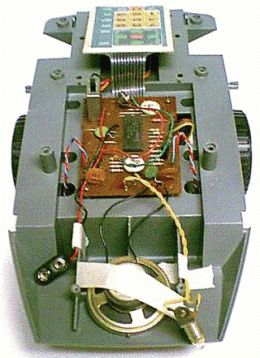 Armed
with an assortment of tools, we carefully poked, prodded
and pried until the Big Trak was
dissected. What we found inside was:
Armed
with an assortment of tools, we carefully poked, prodded
and pried until the Big Trak was
dissected. What we found inside was: - 1 circuit board populated with 2 integrated circuits, 4 transistors and several other miscellaneous components.
- 1 24-key keypad
- 1 light bulb
- 1 speaker
- 1 dual dc-motor gear box with an optical encoder
- 1 9-Volt battery clip
- 1 4-cell D-sized battery box
Our focus quickly turned to the larger of the two ICs found on the circuit board. The IC was labeled TMS1000NLL and being the larger of the two ICs, it would be the microcontroller. If we were going to be able to program the Big Trak to something other than its original functions, the TMS1000 would have to be reprogrammed.
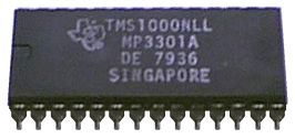 The
TMS1000 Microcontroller was a Texas Instruments
device. All the information that we had on this IC
came from the Ciarcia's Circuit Cellar article which was
quite clear in the fact that this IC could not be
reprogrammed. What we needed was a small,
lightweight computer that could be quickly reprogrammed,
had at least 19 I/O lines and could be powered by
batteries
The
TMS1000 Microcontroller was a Texas Instruments
device. All the information that we had on this IC
came from the Ciarcia's Circuit Cellar article which was
quite clear in the fact that this IC could not be
reprogrammed. What we needed was a small,
lightweight computer that could be quickly reprogrammed,
had at least 19 I/O lines and could be powered by
batteries At the time that we were doing this, we had two computers. A commodore-64 and an Atari 800. After some deliberation on whether or not the Big Trak could hold the weight of one of those computers plus some extra batteries mounted to the top of it, we decided that the Big Trak would just have to stay in its original condition. That is... until 18 years later.
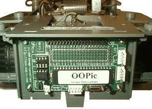 The OOPic
microcontroller is lightweight, fits nicely on the back
of the Big Trak, has 31 I/O lines and requires no
additional batteries other than the ones that the Big
Trak used already. And even with the Big Trak using
19 I/O lines, there are still 12 I/O lines available for
future expansion.
The OOPic
microcontroller is lightweight, fits nicely on the back
of the Big Trak, has 31 I/O lines and requires no
additional batteries other than the ones that the Big
Trak used already. And even with the Big Trak using
19 I/O lines, there are still 12 I/O lines available for
future expansion. To mount the OOPic on the Big Trak, the panel on the back of the Big Trak was removed and 4 holes were drilled into the 4-cell D-sized battery case. The four screws were inserted from inside the battery case and nuts were then put on. This holds the screws in place and provides a stand-off for the OOPic. The OOPic was then placed on the screws, with the 40-pin connector towards the top, and 4 more nuts were added to secure it in place.
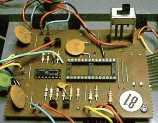 In the Big Trak's
design, the TMS1000 was powered directly by the 9-Volt
battery. This is very convenient because it brought
9-Volts directly to one of the pins on the TMS1000.
As well as the power, all of the I/O used by the
electronics of the Big Trak also connects to the pins of
the TMS1000. Since every connection that the OOPic
needs goes through the 28 pins of the TMS1000, all that
will be needed to connect the OOPic to the Big Trak is a
single 40-pin ribbon cable which will run from the OOPic
to an adapter which will then
plug into the same place that the TMS1000 is connected.
In the Big Trak's
design, the TMS1000 was powered directly by the 9-Volt
battery. This is very convenient because it brought
9-Volts directly to one of the pins on the TMS1000.
As well as the power, all of the I/O used by the
electronics of the Big Trak also connects to the pins of
the TMS1000. Since every connection that the OOPic
needs goes through the 28 pins of the TMS1000, all that
will be needed to connect the OOPic to the Big Trak is a
single 40-pin ribbon cable which will run from the OOPic
to an adapter which will then
plug into the same place that the TMS1000 is connected. Before any connections can be made to the OOPic, the Big Trak's TMS1000 needs to be removed and replaced with a 28-pin socket. When the TMS1000's was desoldered, extra care was given to the traces on the circuit board. Since the circuit board only has traces on one side and the holes are not plated through, it is very easy to have some of the traces lift off of the circuit board. This can happen when too much heat from the soldering iron is applied for too long, which damages the glue that holds the traces to the board.
With the 28-pin socket in place, the original TMS1000 can be plugged back into the Big Trak's circuit board and the Big Trak can be tested to be sure that nothing was damaged in the removal/replacement process.
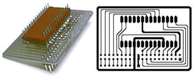 To make
things neat, an adapter was
created that plugs into the Big Trak's new 28-pin
microcontroller socket and has a 40-pin header on it for
the 40-pin cable to connect to. This adapter was
created by making a single sided circuit board.
This board only needs 3 parts. A 28-pin header, which was
soldered onto the bottom of the circuit board, a 40-pin
header, and a 1k resistor.
To make
things neat, an adapter was
created that plugs into the Big Trak's new 28-pin
microcontroller socket and has a 40-pin header on it for
the 40-pin cable to connect to. This adapter was
created by making a single sided circuit board.
This board only needs 3 parts. A 28-pin header, which was
soldered onto the bottom of the circuit board, a 40-pin
header, and a 1k resistor. The circuit board was created using Ivex's Winboard program. An evaluation version of this program, which can be used to print and/or modify the adapter board layout, and the adapter board files can be downloaded free.
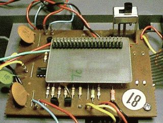 With the adapter plugged into
the Big Trak's new 28-pin socket, the 40-pin cable can
now be attached. The 40-pin cable will need to be
attached in such a way that the ribbon cable goes towards
the left side of the Big Trak because the power switch
prevents it from going the other way.
With the adapter plugged into
the Big Trak's new 28-pin socket, the 40-pin cable can
now be attached. The 40-pin cable will need to be
attached in such a way that the ribbon cable goes towards
the left side of the Big Trak because the power switch
prevents it from going the other way. Notice that there is ample room to make the adapter board larger to accommodate future expansion.
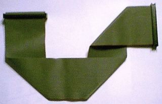 A 40-pin cable from
an IDE hard-drive was used to connect the Big Trak to the
OOPic.
A 40-pin cable from
an IDE hard-drive was used to connect the Big Trak to the
OOPic. First, one of the 40-pin connectors was removed from one end of the cable. Then the remaining 40-pin connector was attached to the adapter's 40-pin header and the cable was folded into a configuration that would take the cable to the side of the Big Trak, which allowed it to go around the keypad connector cable, down to the side of, and then under the keypad's platform, and finally to the back of the Big Trak, where the OOPic was mounted.
Once the cable was folded to size, the 40-pin connector was placed back on the ribbon cable where the cable met the OOPic, and the remaining portion of the ribbon cable was cut off.
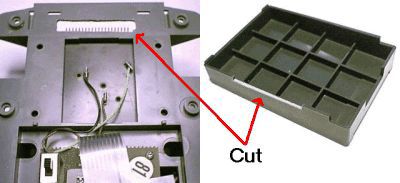 A few modifications were
required to run the 40-pin cable from the electronics of
the Big Trak through the hull and to the OOPic.
A few modifications were
required to run the 40-pin cable from the electronics of
the Big Trak through the hull and to the OOPic. A hole was cut to in the rear of the Big Trak's chassis just over where the OOPic was mounted. This hole needed to be big enough for the 40-pin connector to fit through.
In addition to going through the hole in the back of the chassis, the 40-pin cable needs to slide under the left side of the keyboard platform. The bottom of the keyboard platform sits flush with the chassis, so a small slit, just large enough to allow the ribbon cable to fit under the left side, needed to be cut away.
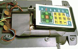 With the modifications made, the
40-pin cable was ready to be installed.
With the modifications made, the
40-pin cable was ready to be installed. First it was connected to the 40-pin header, then it was run down the side of, and then under the keypad's platform, and finally to the back of the Big Trak, where it was connected to the OOPic.
The portion of the cable, that ran down the side of the keypad's platform, was in the way of one of the screw holes. The top shell has a post that extends down to this screw hole, so the cable needed to be rolled up to allow the screw post to meet the hole. This was easy to do, because of the way that the cable was folded.
With the cable installed, the Big Trak was reassembled.
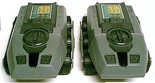 In this front view of two Big
Traks, one retrofitted and one original, you can see that
the retrofit job was non-obtrusive and that nothing
sticks out of the original packaging.
In this front view of two Big
Traks, one retrofitted and one original, you can see that
the retrofit job was non-obtrusive and that nothing
sticks out of the original packaging. 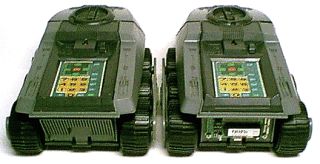 In this back view of two Big
Traks, one retrofitted and one original, you can see that
the only evidence of the retrofit job is that the OOPic
can be seen occupying the space where the panel on the
back of the Big Trak used to be.
In this back view of two Big
Traks, one retrofitted and one original, you can see that
the only evidence of the retrofit job is that the OOPic
can be seen occupying the space where the panel on the
back of the Big Trak used to be. By mounting the OOPic here, the program EEPROM as well as the programming and the I2C networking connections are easily accessible.
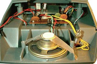 In this view, the Big Trak has
its top in place with the 28-pin to 40-pin adapter
installed. This gives some indication of how much
room the Big Trak has for future enhancements.
In this view, the Big Trak has
its top in place with the 28-pin to 40-pin adapter
installed. This gives some indication of how much
room the Big Trak has for future enhancements.  The OOPic on the Big Trak was
programmed with a duplication of the Big Trak's
original program, thereby making a programmable
programmable Big Trak.
The OOPic on the Big Trak was
programmed with a duplication of the Big Trak's
original program, thereby making a programmable
programmable Big Trak. Also, be sure to check out the Big-O-Trak programming manual, which gives instructions on how to program the Big-O-Trak.