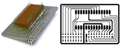
 Every connection that the OOPic
needs in order to be able to control the Big Trak,
goes through the 28 pins of the TMS1000, so an adapter was created that plugs into
a 28-pin socket and has a 40-pin header on it for
the OOPic to connect to. This adapter was created by
making a single sided circuit board. This board only needs 3
parts. A 28-pin header, which was soldered onto the bottom of the
circuit board, a 40-pin header, and a 1k resistor.
Every connection that the OOPic
needs in order to be able to control the Big Trak,
goes through the 28 pins of the TMS1000, so an adapter was created that plugs into
a 28-pin socket and has a 40-pin header on it for
the OOPic to connect to. This adapter was created by
making a single sided circuit board. This board only needs 3
parts. A 28-pin header, which was soldered onto the bottom of the
circuit board, a 40-pin header, and a 1k resistor.
The circuit board was created using Ivex's Winboard program. An evaluation version of this program, which can be used to print and/or modify the adapter board layout, and the adapter board files can be downloaded free.
The following table shows the connections that are made between the 28-pin cable and the 40-pin header:
| OOPic I/O | Function | TMS1000 | TMS1000 | Function | OOPic I/O | |
|---|---|---|---|---|---|---|
| 15 | n/c | 1 | 28 | Optical Encoder | 7 | |
| 14 | Laser | 2 | 27 | n/c | ||
| 13 | Speaker | 3 | 26 | Keypad-1 | 6 | |
| Gnd | Gnd | 4 | 25 | Keypad-2 | 5 | |
| 11 | Keypad-10 | 5 | 24 | Keypad-3 | 24 | |
| 10 | Keypad-9 | 6 | 23 | Keypad-4 | 25 | |
| 9 | Keypad-8 | 7 | 22 | Keypad-5 | 26 | |
| 8 | Keypad-7 | 8 | 21 | Keypad-6 | 27 | |
| Reset | 9 | 20 | +9-Volts | +V | ||
| Speaker | 10 | 19 | Osc | |||
| Gnd | n/c | 11 | 18 | Osc | ||
| 31 | Trailer | 12 | 17 | Speaker | ||
| 30 | RightDriveR | 13 | 16 | LeftDriveF | 29 | |
| 15 | RightDriveF | 14 | 15 | LeftDriveR | 28 |