| EDWARD EVERS | Robot Workshop | Steve's LegWay and More |
In this project, I present some variations of the LegWay design by Steve Hassenplug that utilize the standard LEGO Mindstorms Light sensors in place of the HiTechnic EOPD sensors. The primary motivation for using standard light sensors has been HiTechnic's choice to cease production1 of their RCX compatible sensors. As the EOPD sensors were unavailable and no comparable compatible sensor were found, I chose to experiment with construction and programming variations to achieve the LegWay balancing behavior with the standard light sensors. Again, with much credit to its author, I found that Steve's LegWay code could be adapted, with very minor modifications2, to provide a suitable balancing algorithm for a LegWay with standard light sensors. These modifications also provide the new variants with the ability to balance on a variety of luminously "smooth" and nearly-"smooth" surfaces. This ability was further enhanced by some variations in construction. The major caveat, to this point, is the loss of line following behavior and lack of recovery from spin behavior on less than optimal surfaces in a less than optimal lighting environment.
1. HiTechnic has since resumed production and sales of their specialty sensors.
2. In revision 1, the modifications involved a linear transformation of the raw sensor readings which were fine tuned via menu settings. In revision 2, an improved non-linear mapping replaces the linear mapping and removes the need for menu tweaks.
Changes to the programming(Revision 1):
Changes to the programming(Revision 2):
The HiTechnic EOPD sensors are no longer available, so modifications had to be made to use the standard LEGO light sensors.
The standard LEGO light sensors are very sensitive to variations in the ambient light level.
Stability decrease on darker surfaces. The scaling factor cannot compensate for the lower reflectance.
/*

LegWay

self-balancing robot

by Steve Hassenplug
http://www.geocities.com/stevehassenplug/legway.html

*/

int MotorSpeedArray[32] =  {	1,1,1,1,1,1,1,1, // motor speed 0-7 = forward, 0 = fast, 7 = slow
				3,3,3,3,3,3,3,3, // motor speed 8 = stop
				2,2,2,2,2,2,2,2, // motor speed 9-16 = reverse, 9 = slow, 16 = full
				0,0,0,0,0,0,0,0}; // 24 = float
Analysis of the main program below shows that the MotorSpeedArray is used every 1 millisecond to determine the direction of rotation for each of the LegWay motors: Motor A and Motor C. You will also notice that the speed (power setting) for each motor is hold constant at the maximum value of 255. It is therefore the toggling of direction and duration for which a given state is held that determines the speed of the respective motors.

#include < conio.h >
#include < unistd.h >
#include < dsensor.h >
#include < dmotor.h >
#include < rom/system.h >
#include < dsound.h >
#include < dbutton.h >

int main(int argc, char *argv[])
{
	int L1;
	int MotorA = 0;

	int MotorSetting;

	int L3;
	int MotorC = 0;

	int MotorRunningValue;

	long CheckTime;		// adjust center point
	long AdjustTime;	// adjust for falling
	long FallTime;		// last time < full speed

	int CenterPoint1;
	int CenterPoint3;

// walker variables
	int MoveForward = 1;
	int ForwardDrop = 16;

// spinner variables
	long NextSpin;
	int TurnDirection = 1;
	int EnableSpinner = 0;

	ds_active(&SENSOR_1);
	ds_active(&SENSOR_3);

	motor_a_dir(3);
	motor_c_dir(3);
	motor_a_speed(255);
	motor_c_speed(255);

	L1 = 0;
	L3 = 0;
	MotorSetting = 8;

	msleep(500);  // wait for sensors to power up

	CenterPoint1 = LIGHT_1; // pick a starting center point
	CenterPoint3 = LIGHT_3;

	if ((CenterPoint1 < 3) || (CenterPoint3 < 3)) // only 1 sensor connected
	{
		MoveForward = 0; // do not move forward
		ForwardDrop = 100;
	}

	dsound_system(DSOUND_BEEP);

	while(PRESSED(dbutton(),BUTTON_RUN))
	{
		EnableSpinner = 1;
		MoveForward = 0;
	}


	FallTime = sys_time;
	CheckTime = 0;
	AdjustTime = 0;
	NextSpin = sys_time + 5000;


	while(FallTime + 1000 > sys_time)
	{

// spinner code
		if ((sys_time>NextSpin) && (EnableSpinner == 1))
		{
			MoveForward = MoveForward + TurnDirection;
			NextSpin = sys_time + 1000;
			if ((MoveForward < -5) || ( MoveForward > 5))
			{
				TurnDirection = - TurnDirection;
				NextSpin = sys_time + 5000;
			}
		}
// end spinner

		if (sys_time>AdjustTime) // re-calculate center point based on motorsettings
		{
			CenterPoint1 = (CenterPoint1 + MotorSetting - 8);
			CenterPoint3 = (CenterPoint3 + MotorSetting - 8);
			AdjustTime = sys_time + 50;
		}

		if (sys_time>CheckTime)
		{

			L1 = LIGHT_1;
			L3 = LIGHT_3;

			if (L1 > L3)
			{
				MotorSetting = (CenterPoint1 - L1) / 2 + 8;
				// divide by 2 to slow response down
			}
			else
			{
				MotorSetting = (CenterPoint3 - L3) / 2 + 8;
			}

			// check boundry
			if (MotorSetting < 0) MotorSetting = 0;
			if (MotorSetting > 16) MotorSetting = 16;

			// L1 over black
			if (L1 < L3 - ForwardDrop) MotorA = -MotorSetting; // stop motor A
			else
			{
				if (EnableSpinner == 1)
					MotorA = - MoveForward; // move opposite direction for spin
				else
					MotorA = MoveForward; // move forward
			}

			// L3 over black
			if (L3 < L1 - ForwardDrop) MotorC = -MotorSetting; // stop motor c
			else MotorC = MoveForward; // move forward

			CheckTime = sys_time + 1;
		}

		// less than full power
		if (MotorSetting > 0 && MotorSetting < 16) FallTime = sys_time;

		MotorRunningValue = (sys_time & 7);
		motor_a_dir(MotorSpeedArray[MotorSetting + MotorRunningValue - MotorA]);
		motor_c_dir(MotorSpeedArray[MotorSetting + MotorRunningValue - MotorC]);

		if (((sys_time >> 8) & 2) == 0) // show LegWay on desplay
			cputs("LEG");
		else
			cputs(" WAY");
	}
	motor_a_dir(3);  // stop after fall time expires
	motor_c_dir(3);
	ds_passive(&SENSOR_1);
	ds_passive(&SENSOR_3);
	return 0;
}
Below is a graph, figure 3, that shows the plots of the raw readings from both the HiTechnic EOPD Sensor, in Blue, and the LEGO Light Sensor in Green. A mathematical reference curve of an inverse square mapping of the distance, in Red, shows that the EOPD sensor readings are close to this theoretical model. While the LEGO Light Sensors are clearly far from this model. In order to reuse the balancing code for the EOPD Sensors, it was necessary to find a mathematical mapping from the raw LEGO Light Sensor readings to something close to the EOPD Sensor readings. Such a useful mapping (R_EOPD = (R_LEGO-24)^(1.5)) is show on the graph in yellow.
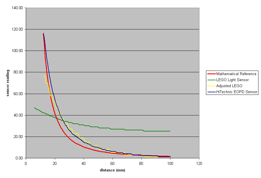
figure 3
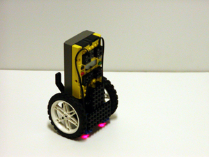
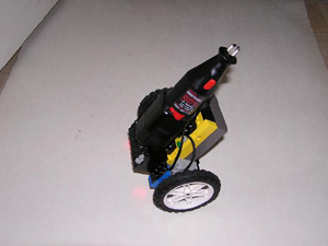
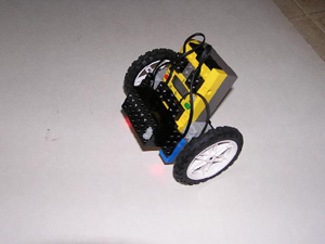
A metal yard stick was place on the table surface with 10 pound weights on either end to keep it from shifting during the measurement process. About twenty pounds of small weights were place in the white mailing box to give it enough inertia to resists movement from being incidentally bumped. A CD jewel case served a squaring tool to position the mailing box at 400 mm. The LegWay was slid along the yard stick from 500mm to 400mm with measurements take at each mm interval. Figures 4,5, and 6 below show the basic setup.
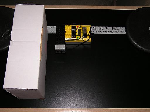
figure 4
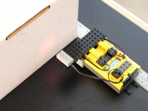
figure 5
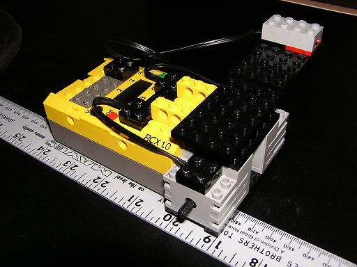
figure 6
Below is a variant of the Hassenplug implementation that has been stripped of the line following and spinning functionality in order to focus on the motor control and sensor handling. You will also notice that a variant of the MotorSpeedArray has been implemented as well as two new support functions: isqrt(), an integer square root function, and ConvertLEGOtoEOPD(), a mapping function from the LEGO light sensor readings to apporimate HiTechnic EOPD sensor readings. This variant of the MotorSpeedArray is a double indexed array that provides results functionally identical to the Hassenplug MotorSpeedArray. Its only purpose here is to illustrate an alternate approach to motor control. There are addition identical variants that can be implemented. Such variants will not be discussed here.
/*

LegWay

self-balancing robot

by Steve Hassenplug
http://www.teamhassenplug.org/robots/legway/

LW_LITE_MCV2.C
This is another variant of the Hassenplug framework limited to balancing
and with a motor control variant that uses a double indexed MotorSpeedArray
to clarify the function of MotorSetting as a index to a particular 8 millisecond
Pulse Modulated Waveform (PMW) template and MotorRunningValue as an index into
the current millisecond of the current PMW template.

As before this variant is functionaly identical to the Hassenplug motor control
implementation.

by: Edward Evers
http://www.edwardevers.com/RobotWorkshop

*/
#include < dsensor.h >
#include < dmotor.h >
#include < dsound.h >
#include < dbutton.h >

MotorDirection MotorSpeedArray[17][8] =
{	{fwd  ,fwd  ,fwd  ,fwd  ,fwd  ,fwd  ,fwd  ,fwd  }, // Forward 8: Full Forward
	{fwd  ,fwd  ,fwd  ,fwd  ,fwd  ,fwd  ,fwd  ,brake}, // Forward 7
	{fwd  ,fwd  ,fwd  ,fwd  ,fwd  ,fwd  ,brake,brake}, // Forward 6
	{fwd  ,fwd  ,fwd  ,fwd  ,fwd  ,brake,brake,brake}, // Forward 5
	{fwd  ,fwd  ,fwd  ,fwd  ,brake,brake,brake,brake}, // Forward 4
	{fwd  ,fwd  ,fwd  ,brake,brake,brake,brake,brake}, // Forward 3
	{fwd  ,fwd  ,brake,brake,brake,brake,brake,brake}, // Forward 2
	{fwd  ,brake,brake,brake,brake,brake,brake,brake}, // Forward 1
	{brake,brake,brake,brake,brake,brake,brake,brake}, // Neutral 0: Neutral
	{brake,brake,brake,brake,brake,brake,brake,rev  }, // Reverse 1
	{brake,brake,brake,brake,brake,brake,rev  ,rev  }, // Reverse 2
	{brake,brake,brake,brake,brake,rev  ,rev  ,rev  }, // Reverse 3
	{brake,brake,brake,brake,rev  ,rev  ,rev  ,rev  }, // Reverse 4
	{brake,brake,brake,rev  ,rev  ,rev  ,rev  ,rev  }, // Reverse 5
	{brake,brake,rev  ,rev  ,rev  ,rev  ,rev  ,rev  }, // Reverse 6
	{brake,rev  ,rev  ,rev  ,rev  ,rev  ,rev  ,rev  }, // Reverse 7
	{rev  ,rev  ,rev  ,rev  ,rev  ,rev  ,rev  ,rev  }  // Reverse 8: Full Reverse
};
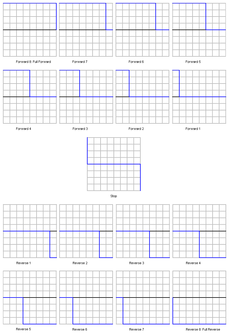
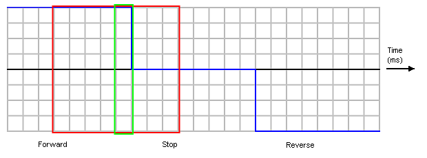
figure 7 - MotorSpeedArray as an array of seventeen 8 millisecond PWM waveforms
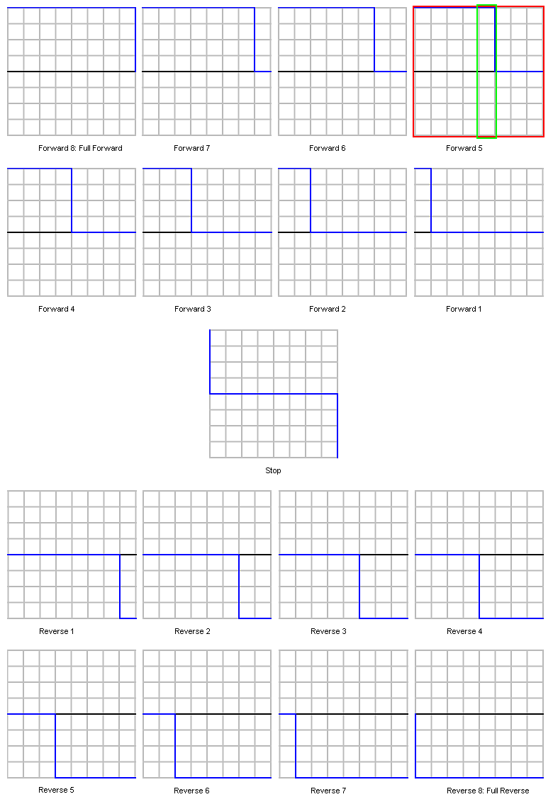
figure 8 - MotorSpeedArray indexed to 8 millisecond "frame" specified by a MotorSetting of 3 (red box) and further index in time by a MotorRunningValue of 4 (green box).
////////////////////////////////////////////////////////////////////////////////
// EE - REV2 code update	02/15/04
////////////////////////////////////////////////////////////////////////////////
#define sys_time get_system_up_time()
////////////////////////////////////////////////////////////////////////////////

#define BITSPERINTEGER (sizeof(int)*8)
#define TOP2BITS(x) (x>>((sizeof(int)*8)-2))

unsigned int isqrt (unsigned int x)
{
    unsigned int i;
    unsigned int a = 0, e = 0, r = 0;


    for (i=0; i < (BITSPERINTEGER >> 1); i++)
	{
        r <<= 2;
        r +=  TOP2BITS(x);
        x <<= 2;

        a <<= 1;
        e  =  (a<<1) | 1;

        if (r >= e)
            {
            r -= e;
            a++;
            }
	}

    return a;
}

int ConvertLEGOtoEOPD( int Lx )
{
	//make sure we don't square root a negative.
	Lx = (Lx<25)?(25):(Lx);

	Lx = (Lx-24);
	Lx = (Lx*Lx*Lx);
	Lx = isqrt(Lx);
	return(Lx);
}

//#define ADJ_LIGHT_1	LIGHT_1
#define ADJ_LIGHT_3	LIGHT_3
#define ADJ_LIGHT_1	ConvertLEGOtoEOPD(LIGHT_1)
//#define ADJ_LIGHT_3	ConvertLEGOtoEOPD(LIGHT_3)

int main(int argc, char *argv[])
{
	int L1;
	int L3;

	int MotorSetting;
	int MotorRunningValue;

	unsigned long CheckTime;		// adjust center point
	unsigned long AdjustTime;	// adjust for falling
	unsigned long FallTime;		// last time < full speed

	int CenterPoint1;
	int CenterPoint3;

	ds_active(&SENSOR_1);
	ds_active(&SENSOR_3);

	motor_a_dir(brake);
	motor_c_dir(brake);
	motor_a_speed(MAX_SPEED);
	motor_c_speed(MAX_SPEED);

	L1 = 0;
	L3 = 0;
	MotorSetting = 8;

	msleep(500);  // wait for sensors to power up

	CenterPoint1 = ADJ_LIGHT_1; // pick a starting center point
	CenterPoint3 = LIGHT_3;

	dsound_system(DSOUND_BEEP);

	FallTime = sys_time;
	CheckTime = 0;
	AdjustTime = 0;

	while(FallTime + 250 > sys_time)
	{
		if (sys_time>AdjustTime) // re-calculate center point based on motorsettings
		{
			CenterPoint1 = (CenterPoint1 + MotorSetting - 8);
			CenterPoint3 = (CenterPoint3 + MotorSetting - 8);
			AdjustTime = sys_time + 56;
		}

		if (sys_time>CheckTime)
		{

			L1 = ADJ_LIGHT_1;
			L3 = LIGHT_3;

			// Use the greater sensor reading
			// to calculate next motor setting.
			if (L1 > L3)
			{
				MotorSetting = (CenterPoint1 - L1) / 2 + 8;
				// divide by 2 to slow response down
			}
			else
			{
				MotorSetting = (CenterPoint3 - L3) / 2 + 8;
			}

			// check boundry
			if (MotorSetting < 0) MotorSetting = 0;
			if (MotorSetting > 16) MotorSetting = 16;

			// Check again in 1ms.
			CheckTime = sys_time + 1;
		}

		// less than full power
		if (MotorSetting > 0 && MotorSetting < 16) FallTime = sys_time;

		MotorRunningValue = (sys_time & 7);
		motor_a_dir(MotorSpeedArray[MotorSetting][MotorRunningValue]);
		motor_c_dir(MotorSpeedArray[MotorSetting][MotorRunningValue]);
	}
	motor_a_dir(brake);  // stop after fall time expires
	motor_c_dir(brake);
	ds_passive(&SENSOR_1);
	ds_passive(&SENSOR_3);
	return 0;
}
| EDWARD EVERS | Robot Workshop | Steve's LegWay and More |
Modified 2005-06-06
Copyright © 2000-2005 Edward Evers